Connecting Multicast Islands with GRE

This post covers how to join together devices requiring multicast connectivity across networks that do not support multicast. This situation is common when the Internet is used for transport, and even in private networks such as MPLS L3VPN if the carrier does not support multicast (or you decided not to pay extra for that service). I will be using Cisco devices and GRE tunnels, though the concepts are generic and apply to multi-vendor networks. First I provide some background on multicast, and then I demonstrate the configuration.
Background:
Multicast routing is one of those topics that is considered more advanced in the field of networking. In fact, in the Cisco Routing & Switching curricula, multicast routing is not mentioned at all until the CCIE level, though other multicast fundamentals such as addressing and the basics of IGMP are covered. Just like with LDP and MPLS L3VPN, Cisco expects you to go from zero to hero at the CCIE level, with no prior introduction at the CCNA or CCNP level inside the R&S track (other tracks do introduce some of the concepts before the CCIE level).
Multicast routing is interesting because it takes many of the rules you learn about normal destination-based forwarding through a multi-hop network and reverses the logic. Multicast routing is concerned with a multicast destination following the reverse path back to the source. The source is the producer of the packets, and the subscribed consumer is the destination. There are different variations and operating models of multicast, including a bidirectional model where multicast sources are also multicast destinations. The other variations are outside the scope of this post, which concerns itself only with PIM-SM with a static RP.
Different multicast routing protocols have been developed over the years, including DVMRP and MOSPF, which are essentially RIP and OSPF respectively for multicast. There have been others as well, but they all fell out of use in favor of PIM: Protocol Independent Multicast (at least within the context of intra-AS multicast routing). The “protocol independent” part comes from the fact that PIM builds the multicast forwarding table (MFIB) based on the unicast forwarding table (FIB). This means however the router’s unicast FIB is populated, whether by one or more routing protocols or static configuration (which can also be considered a routing protocol in itself and in fact some platforms like IOS-XR reference static routes as just another routing protocol), the MFIB uses that information to build the reverse-path tree to the multicast source. Note that the FIB itself is populated from the routing table (RIB). The FIB is essentially all of the routes from the RIB that were chosen for use depending on the rules defined on the router. This means that PIM can be considered an “over the top” service (or an “overlay”), because it requires the underlying unicast routing infrastructure to be in place first.
As you know, TCP builds connections between source and destination on a 1:1 basis using the three-way-handshake. UDP is connectionless, and does not establish a session between source and destination before data is sent. This enables the one-to-many forwarding paradigm, which is why multicast uses UDP. When a multicast router connected to a destination device receives a multicast UDP packet, it performs a reverse path forwarding (RPF) check. The router notes the interface on which the multicast packet arrived, and searches the PIM-built MFIB (based on the unicast FIB) to see if that particular interface would be used for a unicast packet to be sent back toward the source. This is performed for loop prevention because depending on the different paths in the network, the multicast UDP packets could arrive on multiple interfaces.
PIM-SM (sparse mode) uses an RP (Rendezvous Point) as a central meeting place for multicast sources and destinations to find each other. All multicast routers in the PIM-SM domain must know what the unicast IP address is of the RP. This information can be distributed automatically through the proprietary Cisco AutoRP, through the standard Bootstrap Router (BSR) protocol that is part of PIMv2, or through manual configuration. There can be multiple RPs (and in larger networks there most certainly will be for redundancy), and each RP can cover different multicast groups, or they can cover the same groups using Anycast RP with MSDP (multicast source discovery protocol). BSR, Anycast RP, and MSDP are part of the CCIE R&S curricula, but are outside the scope of this post. This post keeps things simple by defining a single static RP which covers the entire multicast address space. This is good enough for most small and even medium-size environments unless the particular multicast application is absolutely critical to your business, in which case you should definitely plan for redundancy.
Multicast IP addresses (224.0.0.0/4 or 224.0.0.0 - 239.255.255.255) are always destinations, never sources. Unicast sources send UDP packets to the multicast destination address. Interested multicast receivers indicate that they wish to receive this multicast traffic by joining the destination multicast group. As mentioned, the RP acts as the meeting point between the senders and the receivers. This is so multiple senders do not need to keep track of multiple receivers, and vice-versa. That is the job of the RP.
As an oversimplification, interested multicast receivers indicate they wish to receive traffic from a particular multicast group by sending an IGMP Join message to their first-hop router. There are exceptions to this, such as with locally-scoped multicast traffic, but that is not covered here. The multicast- enabled first-hop router converts the IGMP Join into a PIM Join, and sends it toward the RP. Each router along the path to the RP maintains state that indicates some device on a particular interface is interested in receiving the traffic. This builds a tree structure throughout the network representing interfaces that wish to receive the particular multicast traffic.
Specifically, this is called a shared tree, and is indicated in multicast
routing tables (show ip mroute) as a (*,G) entry, where G is the multicast
group. When the multicast source sends packets, a multicast shortest-path tree
is built between the source and the receivers. In other words, they both start
by using their shortest paths to the RP through a shared tree, and then the
traffic is placed onto a shortest-path tree between the sender and interested
receivers, which potentially takes the RP out of the multicast forwarding path
for that multicast session. This is indicated by a (S,G) entry in the multicast
routing table, where S is the unicast source and G is multicast group.
When PIM is enabled on an interface, an attempt is made to automatically form PIM neighbor relationships between the routers. With PIM-SM, you must have PIM neighbors established between the receiving first-hop router, the RP, and the multicast source. This is so PIM Join messages can be transferred and the multicast state established indicating where in the network the interested receivers are. As mentioned in the beginning, there are situations where interested multicast receivers are separated from the multicast sender across islands where multicast is not supported (the Internet being a primary example).
GRE tunnels work around this limitation by supporting multicast. True multicast
is performed in hardware. Since GRE tunnels are a software construct, the
multicast traffic essentially becomes “replicated unicast”. Unless a lot of
traffic is being pushed across multiple GRE tunnels, this abstraction should
not be a concern. Since GRE is the basis of technologies like Cisco’s DMVPN,
though, you do need to be aware of the “replicated unicast” nature of the
traffic in a hub-and-spoke environment. This is why the Cisco ip pim nbma-mode command exists. For the
purpose of this post, a simple standard point-to-point GRE tunnel is
configured, which supports the standard multicast configuration just like any
other multicast-capable interface.
Configuration:
This is the simple topology used to demonstrate multicast routing:
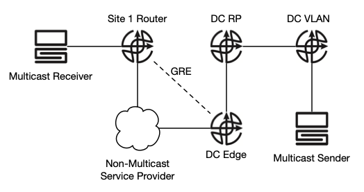
This topology shows a limited number of hops to keep things simple and easy to understand, but it could easily be expanded to more hops as long as each router forms PIM neighbor adjacencies. The multicast sender is in a centralized datacenter, where the RP also exists. The datacenter is separated from “Site 1” by a Layer 3 service that does not support multicast. This could be the Internet or something like a private MPLS L3VPN service without multicast support. I am going to use the private MPLS L3VPN model with BGP as the routing protocol.
The base underlying logical configuration is:
Multicast Receiver: 192.168.1.10/24

Site 1 Router:
 -ip multicast-routing
 -MC Receiver interface: 192.168.1.1/24
   -ip pim sparse-mode
 -WAN interface: 172.31.254.2/30
 -BGP ASN: 64512, redistribute connected
 -ip pim rp-address 10.100.100.1

Service Provider:
 -NO PIM / MULTICAST ROUTING
 -Site 1 interface: 172.31.254.1/30
 -DC interface: 172.31.254.5/30
 -BGP ASN: 64513, redistribute connected

DC Edge Router:
 -ip multicast-routing
 -WAN interface: 172.31.254.6/30
 -BGP ASN: 64514, redistribute connected
 -DC RP interface: 10.255.1.1/30
   -ip pim sparse-mode
 -ip pim rp-address 10.100.100.1
 -OSPF area 0, mutual BGP redistribution

DC RP Router:
 -ip multicast-routing
 -DC Edge interface: 10.255.1.2/30
   -ip pim sparse-mode
 -DC VLAN interface: 10.255.2.2/30
   -ip pim sparse-mode
 -Loopback1 interface: 10.100.100.1/32
   -ip pim sparse-mode
 -OSPF area 0
 -ip pim rp-address 10.100.100.1

DC VLAN Router:
 -ip multicast-routing
 -DC RP interface: 10.255.2.1/30
   -ip pim sparse-mode
 -Multicast Sender interface: 10.1.1.1/24
   -ip pim sparse-mode
 -OSPF area 0
 -ip pim rp-address 10.100.100.1

Multicast Sender: 10.1.1.10/24
I am using routers to simulate the multicast senders and receivers, but they have both unicast and multicast routing disabled, just like a normal host. It is the network infrastructure that enables multicast functionality, not the end devices. End devices have no functional awareness of multicast, they simply send and receive data.
I did not yet configure the GRE tunnel. I first want to establish unicast connectivity between sender and receiver before fixing the currently-broken multicast environment. With all of the unicast pieces in place (BGP routing to the SP from Site 1 and the DC, OSPF within the DC), here is the unicast path from the multicast sender to the multicast receiver:
MCsender# traceroute 192.168.1.10
Type escape sequence to abort.
Tracing the route to 192.168.1.10
VRF info: (vrf in name/id, vrf out name/id)
1 10.1.1.1 1 msec 0 msec 0 msec
2 10.255.2.2 0 msec 1 msec 0 msec
3 10.255.1.1 1 msec 1 msec 0 msec
4 172.31.254.5 1 msec 0 msec 1 msec
5 172.31.254.2 1 msec 0 msec 1 msec
6 192.168.1.10 1 msec * 2 msec
Now let’s explore multicast within the DC site. You can simulate a receiver on
Cisco Layer 3 interfaces with ip igmp join-group MCAST-IP. We’ll use the IP
239.1.2.3 to test. I will join this group from the DC Edge interface that faces
the DC RP router:
DC-Edge(config)# interface e0/1
DC-Edge(config-int)# ip igmp join-group 239.1.2.3
After entering this command, multicast state is introduced into the multicast routing table:
DC-Edge# show ip mroute

<output omitted>

(*, 239.1.2.3), 00:00:31/00:02:28, RP 10.100.100.1, flags: SJPL
  Incoming interface: Ethernet0/1, RPF nbr 10.255.1.2
  Outgoing interface list: Null
At this point, if you run the same command on the DC VLAN router, this group will not be referenced. The group is referenced on the RP though, indicating that multicast signaling has reached the RP:
DC-RP# show ip mroute

(*, 239.1.2.3), 00:03:52/00:02:42, RP 10.100.100.1, flags: SJC
  Incoming interface: Null, RPF nbr 0.0.0.0
  Outgoing interface list:
    Ethernet0/0, Forward/Sparse, 00:03:52/00:02:42
Now let’s start sending multicast packets to the group from the multicast sender. We can do this by pinging the multicast group. While we will be using the host we designated as the sender, there is nothing special about it, and pings could be sent from any device within the contiguous multicast domain and a response should be returned from all devices joined to the group.
MCsender# ping 239.1.2.3 repeat 5
Type escape sequence to abort.
Sending 5, 100-byte ICMP Echos to 239.1.2.3, timeout is 2 seconds:

Reply to request 0 from 10.255.1.1, 11 ms
Reply to request 1 from 10.255.1.1, 2 ms
Reply to request 2 from 10.255.1.1, 1 ms
Reply to request 3 from 10.255.1.1, 1 ms
Reply to request 4 from 10.255.1.1, 1 ms
You send a ping to the multicast group, and the sender receives unicast replies from all devices/interfaces joined to the multicast group (just one, currently). This is one of the areas where you have to consider things in reverse to really understand what is going on. When you configure an interface to join an IGMP group, it is easy to think in client/server terms, with the joined interface acting as a server since it will send back ping replies. With multicast, this is backwards. By joining the interface to the group, you are indicating to the rest of the network that you wish to receive traffic sent to that group, regardless of who the sender is. That’s why even though we used the Multicast Sender device, it can be any device within the multicast domain. It’s true that the Multicast Sender receives a reply from all devices joined to the particular multicast group when it sends out a ping, but those responses are unicast from receiver to sender, not multicast.
Earlier I mentioned how the shared tree (*,G) to the RP is built first, then when traffic starts flowing from sender to receiver, the shortest-path tree is built between the sender and receiver. This is indicated on all PIM routers between the sender and receiver with a (S,G) entry:
DC-VLAN: show ip mroute

(*, 239.1.2.3), 00:04:43/stopped, RP 10.100.100.1, flags: SPF
Incoming interface: Ethernet0/0, RPF nbr 10.255.2.2
Outgoing interface list: Null

(10.1.1.10, 239.1.2.3), 00:00:26/00:03:07, flags: FT
Incoming interface: Ethernet0/1, RPF nbr 0.0.0.0
Outgoing interface list:
Ethernet0/0, Forward/Sparse, 00:00:26/00:03:05
The DC-VLAN router is the first-hop from the Multicast Sender. These two entries reveal the direction of the multicast traffic flow. The shared tree (*,G) entry shows that interface e0/0 has the PIM neighbor 10.255.2.2 toward the RP, 10.100.100.1. The shortest-path tree (S,G) entry shows that e0/1 is the source of the multicast traffic (indicated by no RPF neighbor), and it is sending out e0/0 toward the RP.
Let’s now join the Multicast Receiver interface to the group. We previously verified unicast connectivity between the sender and receiver devices:
MCreceiver(config)# interface e0/0
MCreceiver(config-int)# ip igmp join-group 239.1.2.3
When you issue a ping to 239.1.2.3 from the multicast sender, you still only receive a reply from the previously-configured DC Edge interface (10.255.1.1), despite having unicast connectivity to 192.168.1.10, because the service provider does not support multicast, thereby creating multicast islands.
The first step to remedy this is to create a GRE tunnel between the Site 1 and DC Edge routers, and enable multicast on the tunnel:
Site 1 Router:

interface tunnel 100
 ip address 172.16.100.2 255.255.255.252
 ip pim sparse-mode
 tunnel source e0/0
 tunnel destination 172.31.254.6

DC Edge Router:

interface tunnel 100
 ip address 172.16.100.1 255.255.255.252
 ip pim sparse-mode
 tunnel source e0/0
 tunnel destination 172.31.254.2
While I used the directly-connected interfaces for source and destination, you would typically use loopback interfaces. Now with the Multicast Receiver joined to the group and the multicast-enabled GRE tunnel configured to skip over the non-multicast service provider network, let’s try the ping again from the Multicast Sender:
MCsender# ping 239.1.2.3 repeat 5
Type escape sequence to abort.
Sending 5, 100-byte ICMP Echos to 239.1.2.3, timeout is 2 seconds:

Reply to request 0 from 10.255.1.1, 9 ms
Reply to request 1 from 10.255.1.1, 3 ms
Reply to request 2 from 10.255.1.1, 1 ms
Reply to request 3 from 10.255.1.1, 1 ms
Reply to request 4 from 10.255.1.1, 2 ms
Same results, 192.168.10.1 is not receiving the multicast traffic.
The first step in troubleshooting this is to verify that all Layer 3 interfaces between the sender, receiver(s), and RP have PIM enabled with ip pim sparse- mode on the interface (or sparse-dense mode if you’re using Cisco AutoRP). Then verify that PIM neighbors are formed on all multicast-enabled interfaces between the first-hop routers of the sender and receivers, and the RP:
Site1# show ip pim neighbor
PIM Neighbor Table
Mode: B - Bidir Capable, DR - Designated Router, N - Default DR Priority,
P - Proxy Capable, S - State Refresh Capable, G - GenID Capable
Neighbor Interface Uptime/Expires Ver DR
Address Prio/Mode
172.16.100.1 Tunnel100 00:08:10/00:01:25 v2 1 / S P G
If you continue issuing show ip pim neighbor on all of the routers (except the SP router), you’ll see all neighbors have formed PIM neighborships with each other. You can use the mtrace command to try to determine where the fault is. From the sender’s first-hop router, mtrace from the sender-facing IP address to the receiver’s IP address, and specify the multicast group:
DC-VLAN# mtrace 10.1.1.1 192.168.1.10 239.1.2.3
Type escape sequence to abort.
Mtrace from 10.1.1.1 to 192.168.1.10 via group 239.1.2.3
From source (?) to destination (?)
Querying full reverse path... * switching to hop-by-hop:
0 192.168.1.10
-1 * 192.168.1.10 ==> 0.0.0.0 None Multicast disabled [default]
The mtrace starts at the receiver, and tries to find the reverse multicast path back to the sender’s first-hop router. Despite unicast reachability, we can see that multicast is still broken close to the receiver. The reason is because even though we established the multicast-enabled GRE tunnel, the unicast path is not configured to use the GRE tunnel. PIM follows the unicast path to establish the reverse path. This means we need to alter the multicast routing table.
Static mroutes are used to cause PIM to deviate from the unicast reverse path. Static mroutes work differently than regular static routes, which can be very confusing. Static mroutes tell PIM where the PIM Join messages should be sent to, not how the multicast traffic should flow. The mroute needs to specify the RP and the upstream PIM neighbor. On the router closest to the multicast receiver containing the GRE tunnel endpoint (which happens to be the receiver’s first-hop router in this case), configure the static mroute for the RP toward the PIM neighbor:
Site1(config)# ip mroute 10.100.100.1 255.255.255.255 172.16.100.1
Now let’s try pinging from the multicast sender again:
MCsender# ping 239.1.2.3 repeat 2
Type escape sequence to abort.
Sending 2, 100-byte ICMP Echos to 239.1.2.3, timeout is 2 seconds:

Reply to request 0 from 10.255.1.1, 15 ms
Reply to request 0 from 192.168.1.10, 20 ms
Reply to request 1 from 10.255.1.1, 2 ms
Reply to request 1 from 192.168.1.10, 3 ms
Now we’re getting the results we are looking for! Let’s re-run a couple of the verifications:
DC-VLAN# mtrace 10.1.1.1 192.168.1.10 239.1.2.3
Type escape sequence to abort.
Mtrace from 10.1.1.1 to 192.168.1.10 via group 239.1.2.3
From source (?) to destination (?)
Querying full reverse path...
0 192.168.1.10
-1 172.16.100.2 ==> 172.16.100.2 PIM_MT [using shared tree]
-2 172.16.100.1 ==> 10.255.1.1 PIM [using shared tree]
-3 10.255.1.2 ==> 0.0.0.0 PIM_MT Reached RP/Core [using shared tree]

MCsender# traceroute 192.168.1.10
Type escape sequence to abort.
Tracing the route to 192.168.1.10
VRF info: (vrf in name/id, vrf out name/id)
1 10.1.1.1 1 msec 0 msec 0 msec
2 10.255.2.2 1 msec 0 msec 0 msec
3 10.255.1.1 1 msec 0 msec 1 msec
4 172.31.254.5 0 msec 0 msec 1 msec
5 172.31.254.2 0 msec 1 msec 1 msec
6 192.168.1.10 1 msec * 2 msec
Note the multicast reverse path has changed, but the unicast destination-based path is still the same (and not using the GRE tunnel). The GRE tunnel is used for multicast signaling.
If you have multiple RPs, you can create multiple static mroutes as appropriate. You can also generalize in the same way you do with regular unicast routes. For example, if you have multiple RPs, but they are all present in the 10.100.100.0/24 network, you could issue:
ip mroute 10.100.100.0 255.255.255.0 172.16.100.1
Likewise, with this topology since there is only one exit point from the receiver to the rest of the network, you could create a default mroute:
ip mroute 0.0.0.0 0.0.0.0 172.16.100.1
This causes all PIM Join messages to be sent to 172.16.100.1.
The alternative to using static mroutes is to reconfigure your routing so that the GRE tunnel becomes part of the unicast forwarding path. As anyone who has worked with tunnels and routing protocols knows, this can be very tricky because you have to be careful to not create a recursive routing problem by advertising the tunnel endpoints into the routing protocol used over the tunnel itself. Despite requiring an extra set of knowledge, it can actually be easier to just use static mroutes as we have done here, instead of fooling around with recursive routing issues.
There are many great books, configuration guides and white papers on multicast. Like most people, I started with Beau Williamson’s classic “Developing IP Multicast Networks”. This book provides great foundational knowledge, but was written in 1999 when many of the multicast standards were still under development. This book is great for a history lesson, but for a more modern understanding of multicast applications, I highly recommend Jeff Doyle’s second edition of Routing TCP/IP Volume II published in 2016. Then if you need to dive even deeper into multicast, there are two recent books: IP Multicast, Volume I: Cisco IP Multicast Networking and IP Multicast, Volume II: Advanced Multicast Concepts and Large-Scale Multicast Design, both by Arvind Durai, Ray Blair, and Josh Loveless. I have not read these two books yet, but they look like they could be a great reference.
Multicast routing, like all other forms of routing, contains its own terminology, rules, and sets of nerd/wanker knobs. The difference with multicast is that you really need to understand how routing works normally before you try to reverse everything. Troubleshooting more advanced scenarios takes both patience and experience. Keep working at it, you’ll get it eventually. :-)